PCM modulation
In digital audio using pulse-code modulation (PCM), bit depth is the number of bits of information in each sample, and it directly corresponds to the resolution of each sample. Examples of bit depth include Compact Disc Digital Audio, which uses 16 bits per sample, and DVD-Audio and Blu-ray Disc, which can support up to 24 bits per sample. The most common format for binary representation for the samples is 2’s complement (see the text below).
Binary representation
A PCM signal is a sequence of digital audio samples containing the data providing the necessary information to reconstruct the original analog signal. Each sample represents the amplitude of the signal at a specific point in time, and the samples are uniformly spaced in time. The amplitude is the only information explicitly stored in the sample, and it is typically stored as either an integer or a floating point number, encoded as a binary number with a fixed number of digits: the sample’s bit depth.
The resolution indicates the number of discrete values that can be represented over the range of analog values. The resolution of binary integers increases exponentially as the word length increases. Adding one bit doubles the resolution, adding two quadruples it and so on. The number of possible values that can be represented by an integer bit depth can be calculated by using 2^n, where n is the bit depth. Thus, a 16-bit system has a resolution of 65,536 (2^16) possible values. Integer PCM audio data is typically stored as signed numbers in two’s complement format.
Many audio file formats and digital audio workstations (DAWs) now support PCM formats with samples represented by floating point numbers. Both the WAV file format and the AIFF file format support floating point representations. Unlike integers, whose bit pattern is a single series of bits, a floating point number is instead composed of separate fields whose mathematical relation forms a number. The most common standard is IEEE 754 which is composed of three fields: a sign bit which represents whether the number is positive or negative, an exponent and a mantissa which is raised by the exponent. The mantissa is expressed as a binary fraction in IEEE base-two floating point formats.
In mathematics, positive numbers (including zero) are represented as unsigned numbers. That is we do not put the +ve sign in front of them to show that they are positive numbers.
However, when dealing with negative numbers we do use a -ve sign in front of the number to show that the number is negative in value and different from a positive unsigned value, and the same is true with signed binary numbers.
However, in digital circuits there is no provision made to put a plus or even a minus sign to a number, since digital systems operate with binary numbers that are represented in terms of “0’s” and “1’s”. When used together in microelectronics, these “1’s” and “0’s”, called a bit (being a contraction of BInary digiT), fall into several range sizes of numbers which are referred to by common names, such as a byte or a word.
We have also seen previously that an 8-bit binary number (a byte) can have a value ranging from 0 (000000002) to 255 (111111112), that is 28 = 256 different combinations of bits forming a single 8-bit byte. So for example an unsigned binary number such as: 010011012 = 64 + 8 + 4 + 1 = 7710 in decimal. But Digital Systems and computers must also be able to use and to manipulate negative numbers as well as positive numbers.
Mathematical numbers are generally made up of a sign and a value (magnitude) in which the sign indicates whether the number is positive, ( + ) or negative, ( – ) with the value indicating the size of the number, for example 23, +156 or -274. Presenting numbers is this fashion is called “sign-magnitude” representation since the left most digit can be used to indicate the sign and the remaining digits the magnitude or value of the number.
Sign-magnitude notation is the simplest and one of the most common methods of representing positive and negative numbers either side of zero, (0). Thus negative numbers are obtained simply by changing the sign of the corresponding positive number as each positive or unsigned number will have a signed opposite, for example, +2 and -2, +10 and -10, etc.
But how do we represent signed binary numbers if all we have is a bunch of one’s and zero’s. We know that binary digits, or bits only have two values, either a “1” or a “0” and conveniently for us, a sign also has only two values, being a “+” or a “–“.
Then we can use a single bit to identify the sign of a signed binary number as being positive or negative in value. So to represent a positive binary number (+n) and a negative (-n) binary number, we can use them with the addition of a sign.
For signed binary numbers the most significant bit (MSB) is used as the sign bit. If the sign bit is “0”, this means the number is positive in value. If the sign bit is “1”, then the number is negative in value. The remaining bits in the number are used to represent the magnitude of the binary number in the usual unsigned binary number format way.
Then we can see that the Sign-and-Magnitude (SM) notation stores positive and negative values by dividing the “n” total bits into two parts: 1 bit for the sign and n–1 bits for the value which is a pure binary number. For example, the decimal number 53 can be expressed as an 8-bit signed binary number as follows.
Positive Signed Binary Numbers

Negative Signed Binary Numbers

-2(n-1) to +2(n-1)
So for example: if we have 4 bits to represent a signed binary number, (1-bit for the Sign bitand 3-bits for the Magnitude bits), then the actual range of numbers we can represent in sign-magnitude notation would be:
-2(4-1) – 1 to +2(4-1) – 1
-2(3) – 1 to +2(3) – 1
-7 to +7
Whereas before, the range of an unsigned 4-bit binary number would have been from 0 to15, or 0 to F in hexadecimal, we now have a reduced range of -7 to +7. Thus an unsigned binary number does not have a single sign-bit, and therefore can have a larger binary range as the most significant bit (MSB) is just an extra bit or digit rather than a used sign bit.
Another disadvantage here of the sign-magnitude form is that we can have a positive result for zero, +0 or 00002, and a negative result for zero, -0 or 10002. Both are valid but which one is correct.
Signed Binary Numbers Example No1
Convert the following decimal values into signed binary numbers using the sign-magnitude format:
| -1510 as a 6-bit number | ⇒ | 1011112 |
| +2310 as a 6-bit number | ⇒ | 0101112 |
| -5610 as a 8-bit number | ⇒ | 101110002 |
| +8510 as a 8-bit number | ⇒ | 010101012 |
| -12710 as a 8-bit number | ⇒ | 111111112 |
The sign-magnitude representation of a binary number is a simple method to use and understand for representing signed binary numbers, as we use this system all the time with normal decimal (base 10) numbers in mathematics. Adding a “1” to the front of it if the binary number is negative and a “0” if it is positive.
However, using this sign-magnitude method can result in the possibility of two different bit patterns having the same binary value. For example, +0 and -0 would be 0000 and 1000 respectively as a signed 4-bit binary number. So we can see that using this method there can be two representations for zero, a positive zero ( 00002 ) and also a negative zero ( 10002 ) which can cause big complications for computers and digital systems.
One’s Complement of a Signed Binary Number
One’s Complement or 1’s Complement as it is also termed, is another method which we can use to represent negative binary numbers in a signed binary number system. In one’s complement, positive numbers (also known as non-complements) remain unchanged as before with the sign-magnitude numbers.
Negative numbers however, are represented by taking the one’s complement (inversion, negation) of the unsigned positive number. Since positive numbers always start with a “0”, the complement will always start with a “1” to indicate a negative number.
The one’s complement of a negative binary number is the complement of its positive counterpart, so to take the one’s complement of a binary number, all we need to do is change each bit in turn. Thus the one’s complement of “1” is “0” and vice versa, then the one’s complement of 100101002 is simply 011010112 as all the 1’s are changed to 0’s and the 0’s to 1’s.
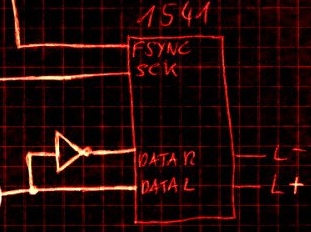
The easiest way to find the one’s complement of a signed binary number when building digital arithmetic or logic decoder circuits is to use Inverters. The inverter is naturally a complement generator and can be used in parallel to find the 1’s complement of any binary number as shown.
1’s Complement Using Inverters

Addition and Subtraction Using One’s Complement
One of the main advantages of One’s Complement is in the addition and subtraction of two binary numbers. In mathematics, subtraction can be implemented in a variety of different ways as A – B, is the same as saying A + (-B) or -B + A etc. Therefore, the complication of subtracting two binary numbers can be performed by simply using addition.
We saw in the Binary Adder tutorial that binary addition follows the same rules as for the normal addition except that in binary there are only two bits (digits) and the largest digit is a “1”, (just as “9” is the largest decimal digit) thus the possible combinations for binary addition are as follows:
| 0 | 0 | 1 | 1 | |
| + 0 | + 1 | + 0 | + 1 | |
| 0 | 1 | 1 | 1← 0 | ( 0 plus a carry 1 ) |
Subtraction of Two Binary Numbers
An 8-bit digital system is required to subtract the following two numbers 115 and 27 from each other using one’s complement. So in decimal this would be: 115 – 27 = 88.
First we need to convert the two decimal numbers into binary and make sure that each number has the same number of bits by adding leading zero’s to produce an 8-bit number (byte). Therefore:
11510 in binary is: 011100112
2710 in binary is: 000110112
Now we need to find the complement of the second binary number, (00011011) while leaving the first number (01110011) unchanged. So by changing all the 1’s to 0’s and 0’s to 1’s, the one’s complement of 00011011 is therefore equal to 11100100.
Adding the first number and the complement of the second number gives:
| 01110011 |
| + 11100100 |
| Overflow → 1 01010111 |
The 8-bit result from above is: 01010111 (the overflow “1” cancels out) and to convert it back from a one’s complement answer to the real answer we now have to add “1” to the one’s complement result, therefore:
| 01010111 |
| + 1 |
| 01011000 |
Then we can see that signed or unsigned binary numbers can be subtracted from each other using One’s Complement and the process of addition. Binary adders such as the TTL 74LS83 or 74LS283 can be used to add or subtract two 4-bit signed binary numbers or cascaded together to produce 8-bit adders complete with carry-out.
Two’s Complement of a Signed Binary Number
Two’s Complement or 2’s Complement as it is also termed, is another method like the previous sign-magnitude and one’s complement form, which we can use to represent negative binary numbers in a signed binary number system. In two’s complement, the positive numbers are exactly the same as before for unsigned binary numbers. A negative number, however, is represented by a binary number, which when added to its corresponding positive equivalent results in zero.
In two’s complement form, a negative number is the 2’s complement of its positive number with the subtraction of two numbers being A – B = A + ( 2’s complement of B ) using much the same process as before as basically, two’s complement is one’s complement + 1.
The main advantage of two’s complement over the previous one’s complement is that there is no double-zero problem plus it is a lot easier to generate the two’s complement of a signed binary number. Therefore, arithmetic operations are relatively easier to perform when the numbers are represented in the two’s complement format.
Let’s look at the subtraction of our two 8-bit numbers 115 and 27 from above using two’s complement, and we remember from above that the binary equivalents are:
11510 in binary is: 011100112
2710 in binary is: 000110112
Our numbers are 8-bits long, then there are 28 digits available to represent our values and in binary this equals: 1000000002 or 25610. Then the two’s complement of 2710 will be:
(28)2 – 00011011 = 100000000 – 00011011 = 111001012
The complementation of the second negative number means that the subtraction becomes a much easier addition of the two numbers so therefore the sum is: 115 + ( 2’s complement of 27 ) which is:
01110011 + 11100101 = 1 010110002
As previously, the 9th overflow bit is disregarded as we are only interested in the first 8-bits, so the result is: 010110002 or (64 + 16 + 8) = 8810 in decimal the same as before.
Signed Binary Numbers Summary
We have seen that negative binary numbers can be represented by using the most significant bit (MSB) as a sign bit. If an n bit binary number is signed the leftmost bit is used to represent the sign leaving n-1 bits to represent the number.
For example, in a 4-bit binary number, this leaves only 3 bits to hold the actual number. If however, the binary number is unsigned then all the bits can be used to represent the number.
The representation of a signed binary number is commonly referred to as the sign-magnitude notation and if the sign bit is “0”, the number is positive. If the sign bit is “1”, then the number is negative. When dealing with binary arithmetic operations, it is more convenient to use the complement of the negative number.
Complementation is an alternative way of representing negative binary numbers. This alternative coding system allows for the subtraction of negative numbers by using simple addition.
Since positive sign-magnitude numbers always start with a zero (0), its complement will therefore always start with a one (1) to indicate a negative number as shown in the following table.
4-bit Signed Binary Number Comparison
| Decimal | Signed Magnitude | Signed One’s Complement | Signed Two’s Complement |
| +7 | 0111 | 0111 | 0111 |
| +6 | 0110 | 0110 | 0110 |
| +5 | 0101 | 0101 | 0101 |
| +4 | 0100 | 0100 | 0100 |
| +3 | 0011 | 0011 | 0011 |
| +2 | 0010 | 0010 | 0010 |
| +1 | 0001 | 0001 | 0001 |
| +0 | 0000 | 0000 | 0000 |
| -0 | 1000 | 1111 | – |
| -1 | 1001 | 1110 | 1111 |
| -2 | 1010 | 1101 | 1110 |
| -3 | 1011 | 1100 | 1101 |
| -4 | 1100 | 1011 | 1100 |
| -5 | 1101 | 1010 | 1011 |
| -6 | 1110 | 1001 | 1010 |
| -7 | 1111 | 1000 | 1001 |
The method of 2’s complement arithmetic is commonly used in computers to handle negative numbers the only disadvantage is that if we want to represent negative binary numbers in the signed binary number format, we must give up some of the range of the positive number we had before.
Some errors in the designs of DACs
 There exist a lot of ‘improved’ designs for audio DACs. For example the common used idea is to make the dual DAC balanced. That means it will not work as one stereo DAC but will be used for one channel only with XLR balanced outputs. This approach require the data for the one of the internal DAC to be inverted and the common way is to use inverters. Yes it will work but mathematically it will cause a some small distortion as the input signal is 2’s complemented and it cannot be inverse just by using inverters just like 1’s complemented signal. The right way to do the inversion is by adding ‘1’ to the inverse digit, which is not so easy to do because it will require external shift registers, lathes and adders.
Apparently many DACs that use I2S architecture (and related chipsets) do not correctly convert 16 bit samples to 24 or 32 bit words prior to conversion. LSB extension error under I2S: this problem started out during the transition from 32 FS (16 bit) to 64 FS clocking to accommodate sample lengths above 16 bits. Under the I2S spec, the LSB extension of a 16 bit sample to 24 or 32 bits is accomplished by simply adding bits set to zero. Seems reasonable by itself. However, the samples are represented internally in 2’s complement format, so in the case of positive numbers, one should extend the word length by adding the MSB (0) to the tail, and for negative numbers, adding the MSB (1) to the tail. Thus, 50% of the time, namely for the negative samples as represented in 2’s complement mode, the I2S convention is incorrectly forcing the LSBs to be 0, which introduces an error or distortion. Some examples for a 16 to 32 bit extension (MSB on the left):
Full scale sample:
1111 1111 1111 1111 under I2S becomes 1111 1111 1111 1111 0000 0000 0000 0000
1111 1111 1111 1111 in correct 2s comp 1111 1111 1111 1111 1111 1111 1111 1111
This error (the 16 LSBs set to 0 instead of 1) gives a distortion of 0.0015% of roughly -96 dB. (subtract incorrectly formatted sample from correctly formatted sample, divided by the correctly formatted sample).
For somewhat less than full scale sample:
1000 1111 1111 1111 under I2S becomes 1010 1111 1111 1111 0000 0000 0000 0000
1000 1111 1111 1111 in correct 2s comp 1000 1111 1111 1111 1111 1111 1111 1111
This time the error is about -66 dB.