Phase compensation is a method for correcting the time problems on spectrum in magnetic audio recording. These compensation networks are provided for the record amplifier circuitry, also for playback amplifier. These networks enable the circuit to be optimally compensated for group delay introduced by the record equalization circuitry with separate adjustments for both operating speeds. The result is superior transient and square wave response as well as higher recording level capability with complex waveforms before saturation occurs.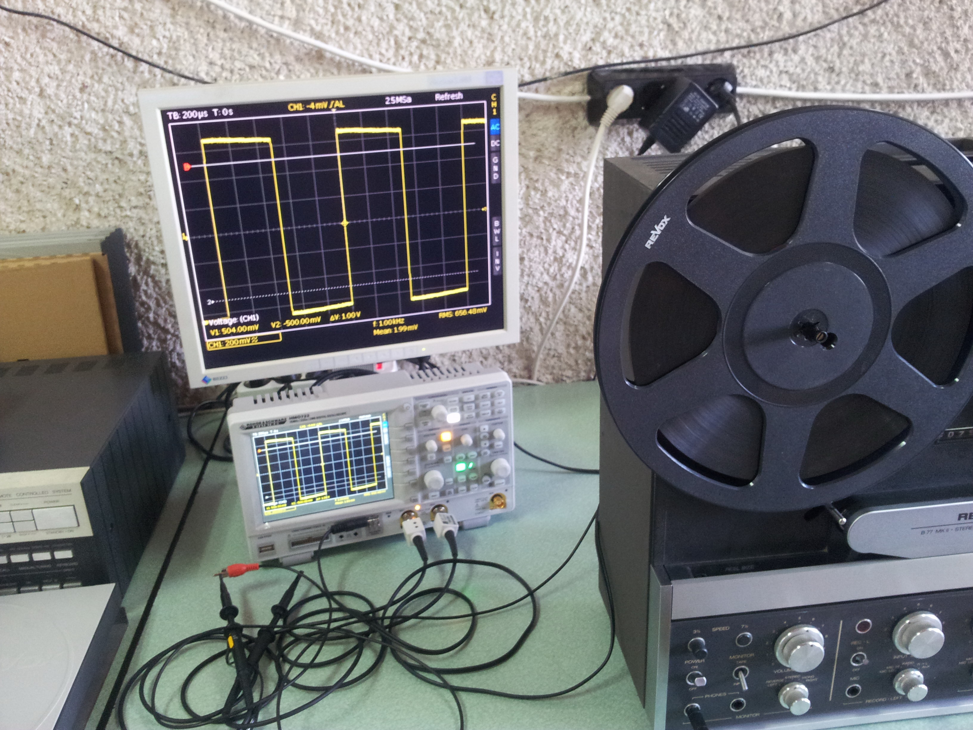
LAB2104 team made a compensated circuit for Revox B77 tape recorder. The first diagram shows the original 1kHz signal from the source. A square wave is a non-sinusoidal periodic waveform (which can be represented as an infinite summation of sinusoidal waves), in which the amplitude alternates at a steady frequency between fixed minimum and maximum values, with the same duration at minimum and maximum. On the second photo you can see the distortion of the recorded signal on the tape. You can see that the rising and falling fronts are very flat compared to the original signal. This is caused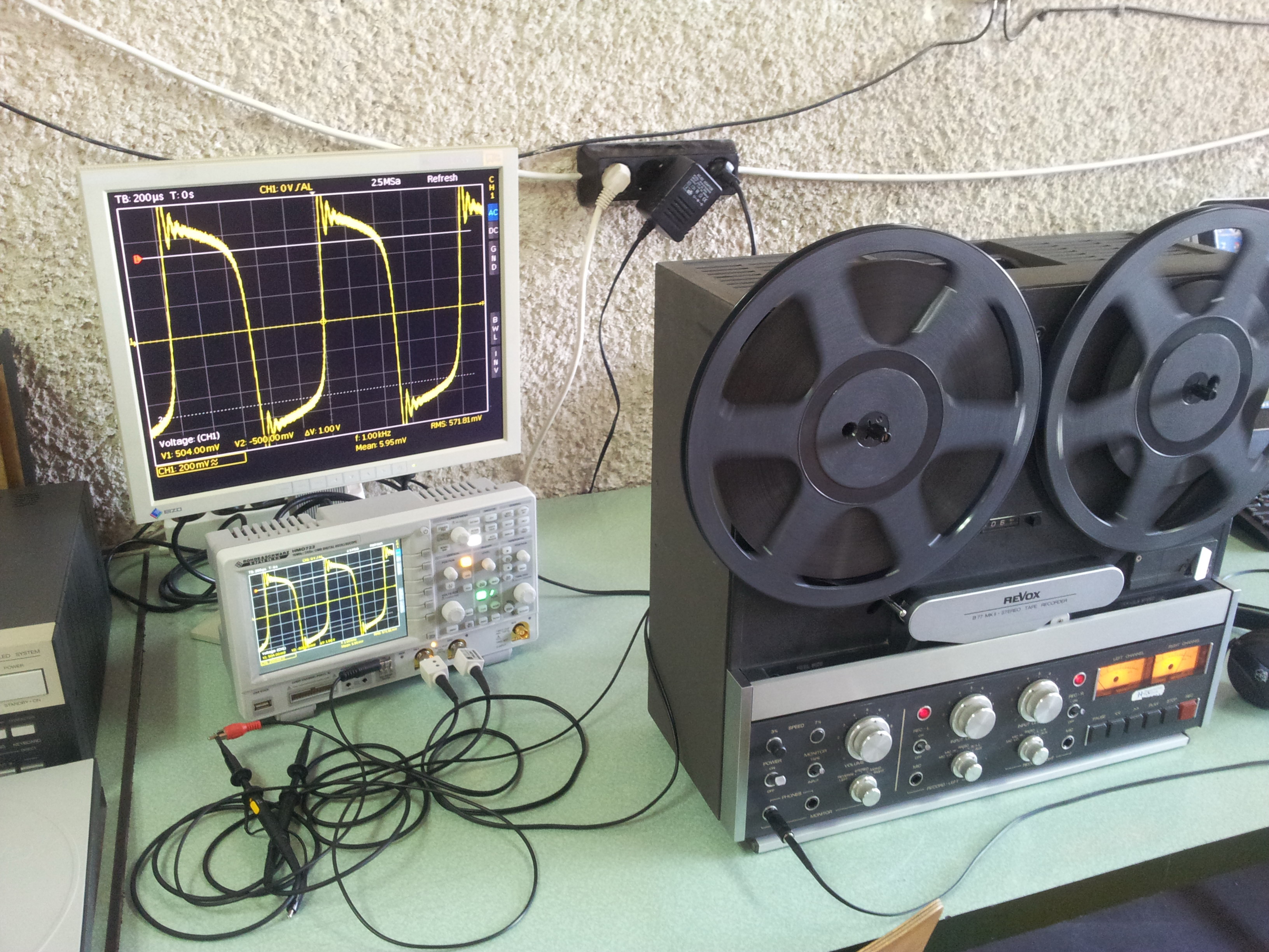 by delay problems and distortions that change the phase of the high frequency harmonics. After summing these harmonica cannot produce the original square wave signal, also the energy of the recorded signal is not focused in time as the original.
OK, lets change the input signal from 1 kHz to 3 kHz. There are many musical instruments with base spectrum around 3 kHz, like cymbals. Fortunately, cymbals remain fairly constant and predictable over many types of music. Their dominant energy lies in the 2 kHz to 5 kHz region. Cymbal 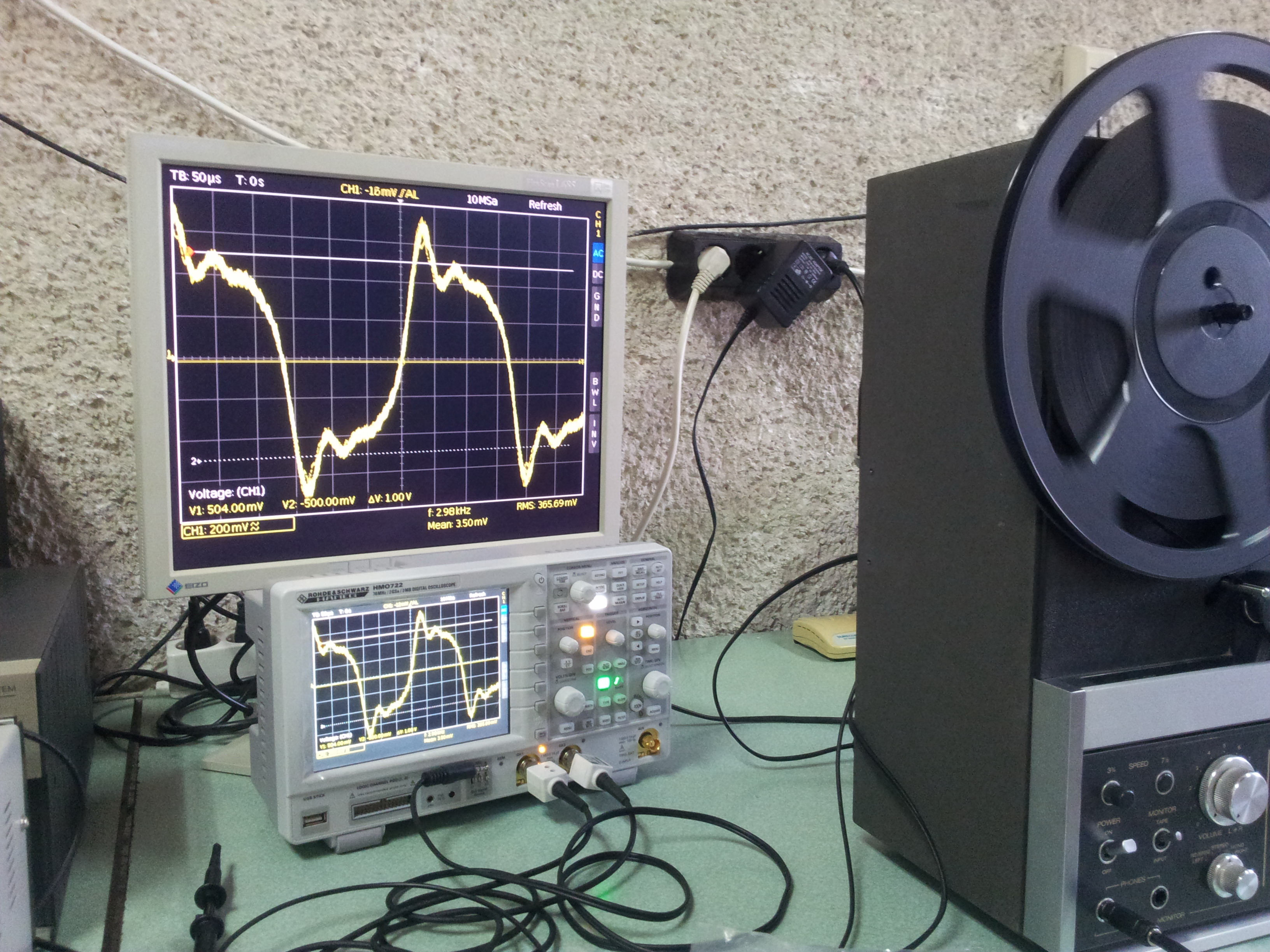 harmonics extend up to and past the range of human hearing. Boosting of cymbals in the 10 kHz to 12 kHz region results in a very brittle sound. Usually, boosts in the dominant area of 2 kHz to 3 kHz makes the overall mix less “wet” or “noisy” than boosting in the upper region. For clear cymbals it is required the high frequency components to be in phase with the dominant base area. Now let see the distortion of the recorded signals of the 3 kHz square wave. You can see more waveform distortion compared to the 1 kHz square wave signal. That means the energy is not correctly distributed in time.
 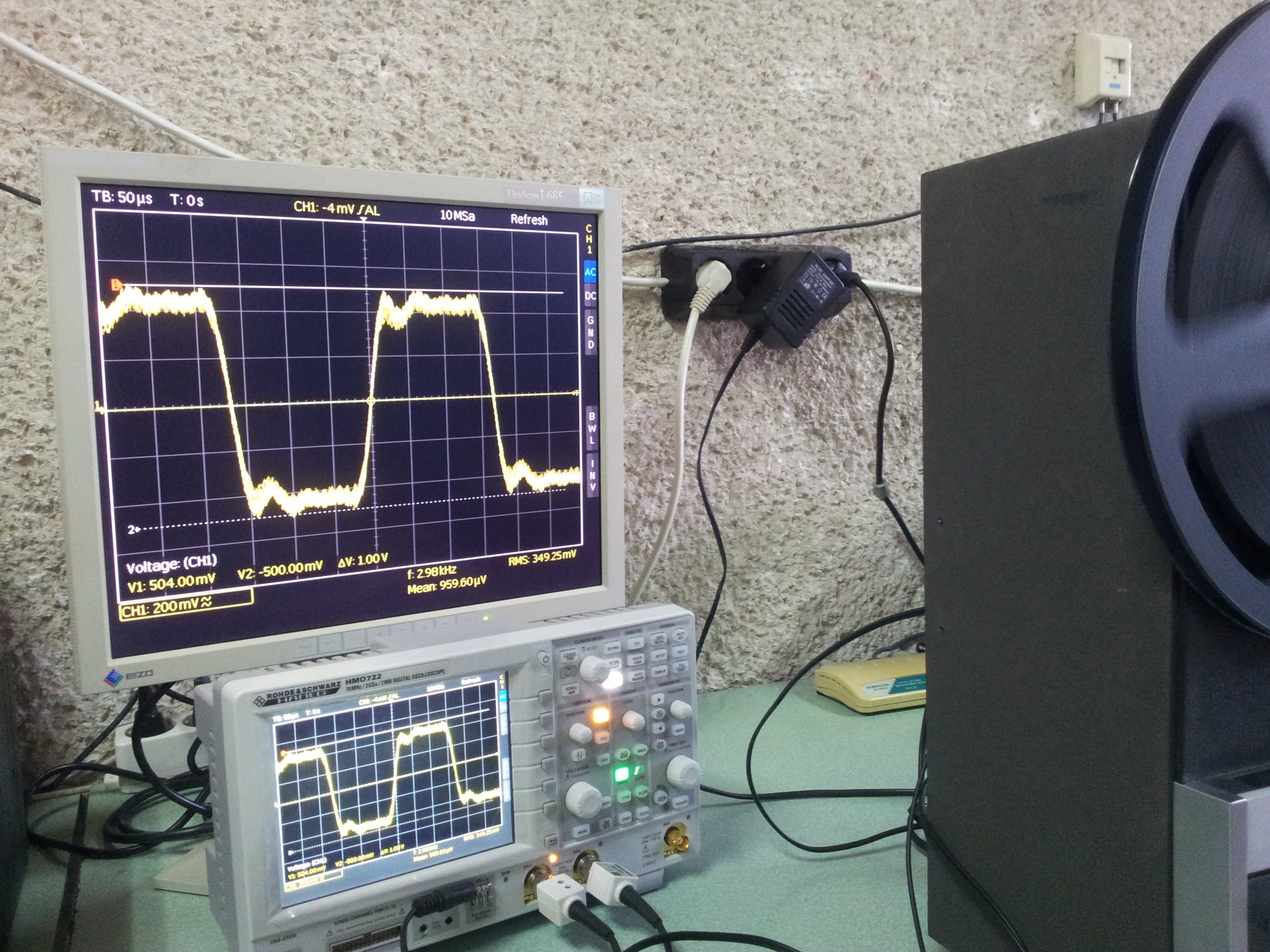 OK, let see the effect of the custom made phase compensated circuit for this signal on the next photo. You can see that the form is more close to the original square wave signal. The fact is that the phase correction cause the energy of the high frequency harmonics to be correlated in time.
The LAB2104 team made testbench of this phase compensation circuit for the tape speed of 7 ½ ips. After that a simulation was started to verify the final results. You can notice that this phase compensation network do not reflect to the frequency response. The frequency response is flat from 0 Hz to 25 kHz. The circuit changes only the phase of the signal. 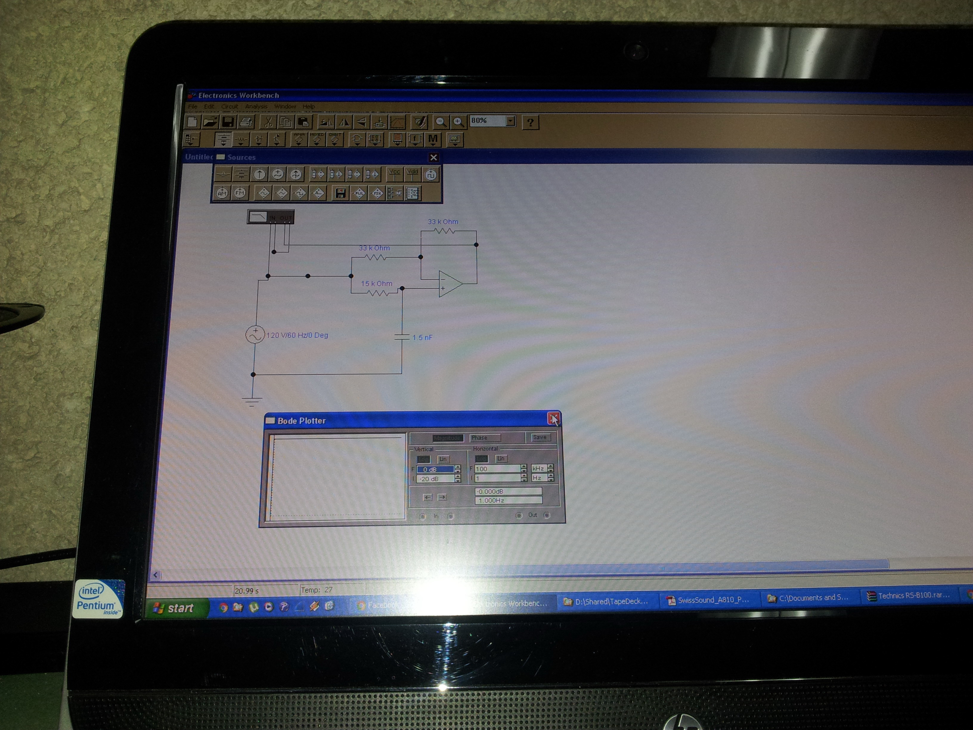 On the next photos you can see the test bench and the simulation charts.
One interesting question is about the form of the reversed phase components. On the testbench you can see the reverse pre-distortion that compensates the recording phase problems. The input signal is square wave 3 kHz and after it goes through the compensation network, it changes as on the photo. Then this pre-compensated signal goes to the standard recording chain (line and recording amplifiers). After the phase change in recording circuits, the form from the playback amplifier goes close to the square wave. On the next photo you can see more precisely how the pre-compensated square wave signal looks like. 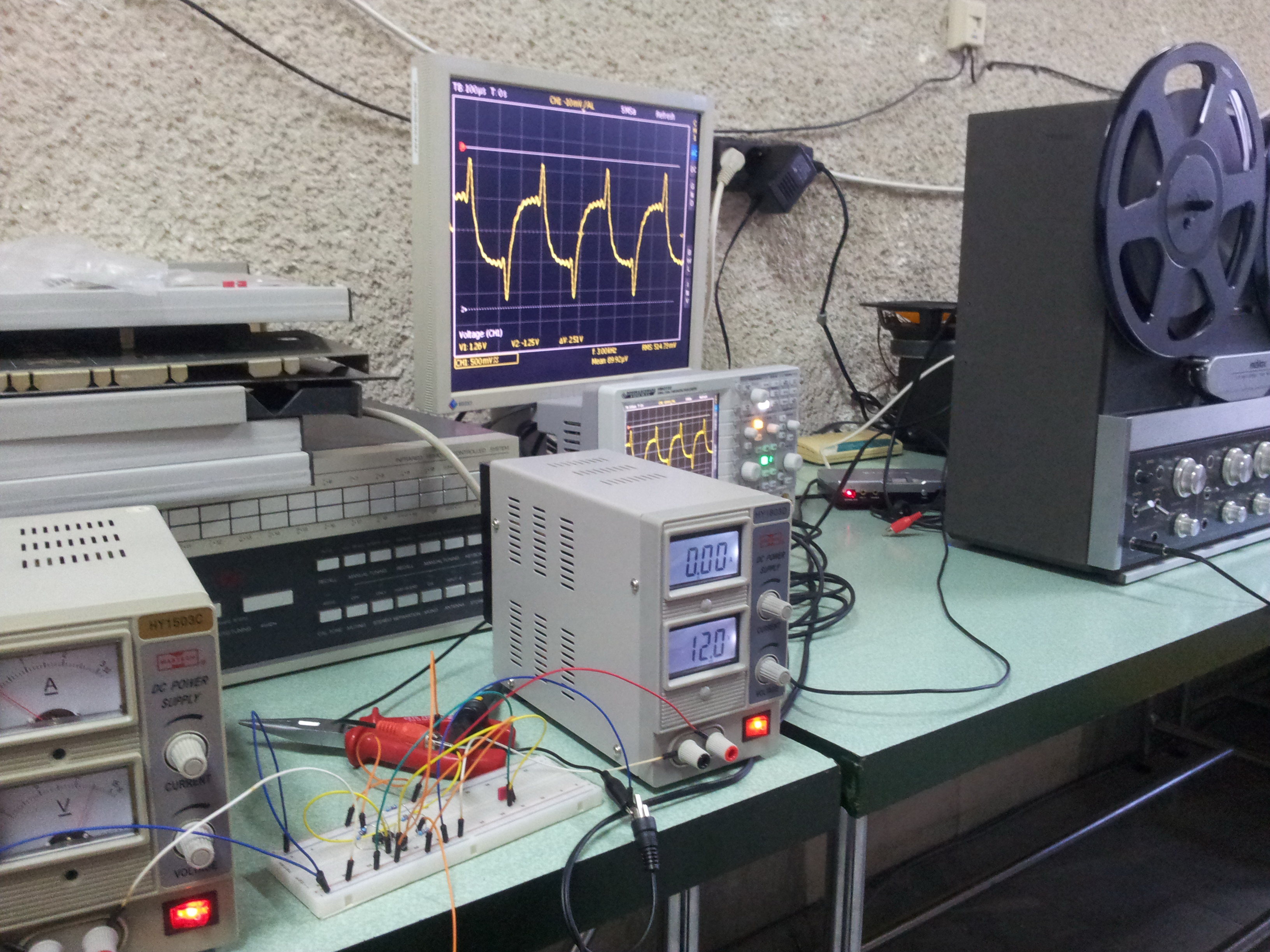
Lets start talking about the ways for correcting the phase (methods for phase correction). The first tape recorder, which uses phase correction was Studer A810. Now some professional tape recorders like Otari MTR12 and MTR90 also include compensation networks. The first idea from A810 was to correct the phase on high frequency recording chain, which is used to compensate head loss and tape loss from self demagnetization. It is hard to do due complex signal processing, which makes signal path longer. 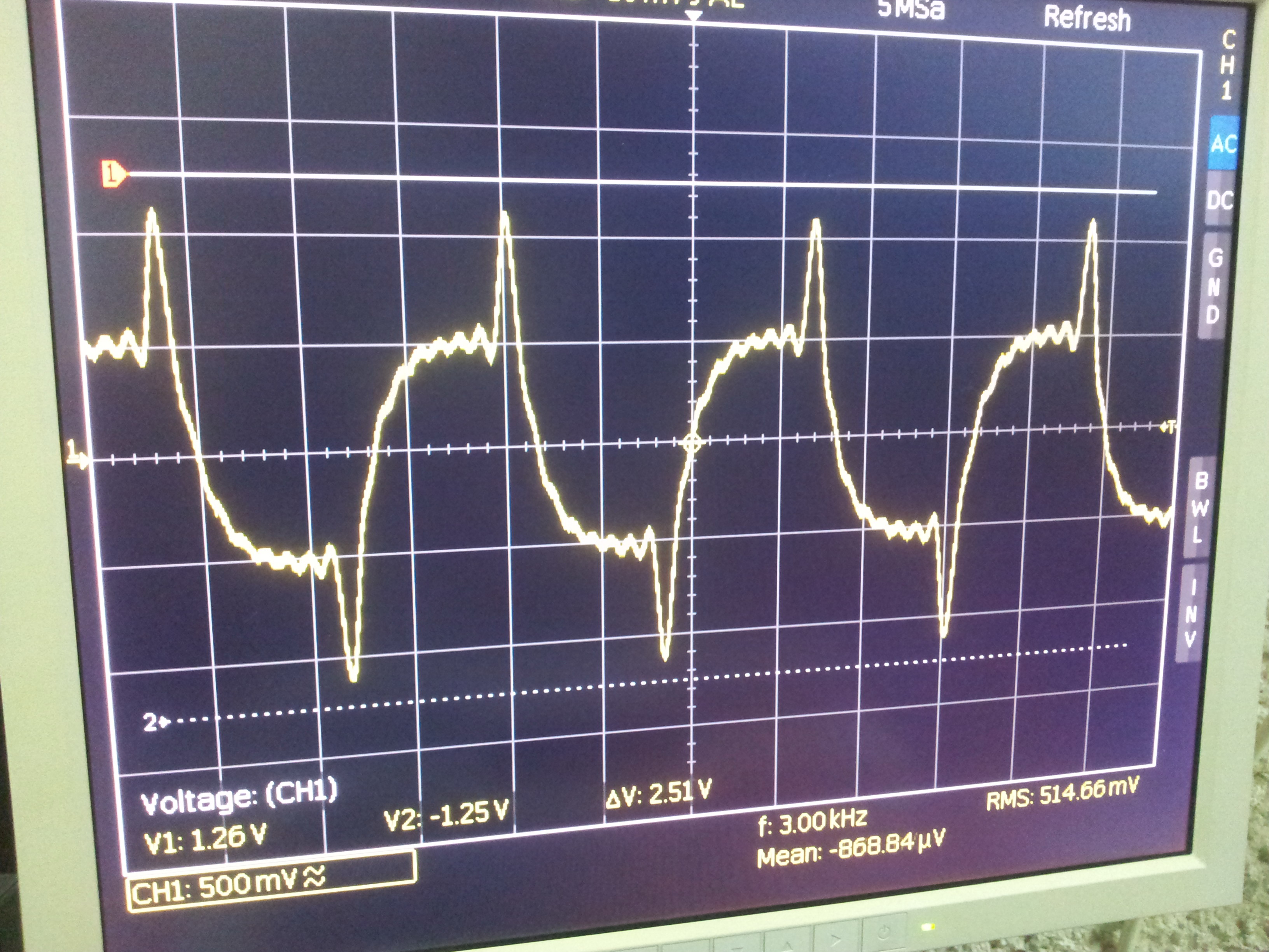 You can see the original publication [1] by the Revox team with some mathematics inside. There you can see the effect of the compensated signal of the 2.5 kHz square wave. One reasonable question is when the compensation is enough? If the compensation is deeper, the final effect is worst. If the compensation is very light, the effect is still insufficient to make the focus on high frequency components. There is one good criteria for the depth of the compensation. It is based on the peaks of the waveform on rising and the falling edges of the product signal (playback signal from the tape). The first rising edge oscillations must be inside the last peak on falling edge. This is illustrated on the final diagram.
 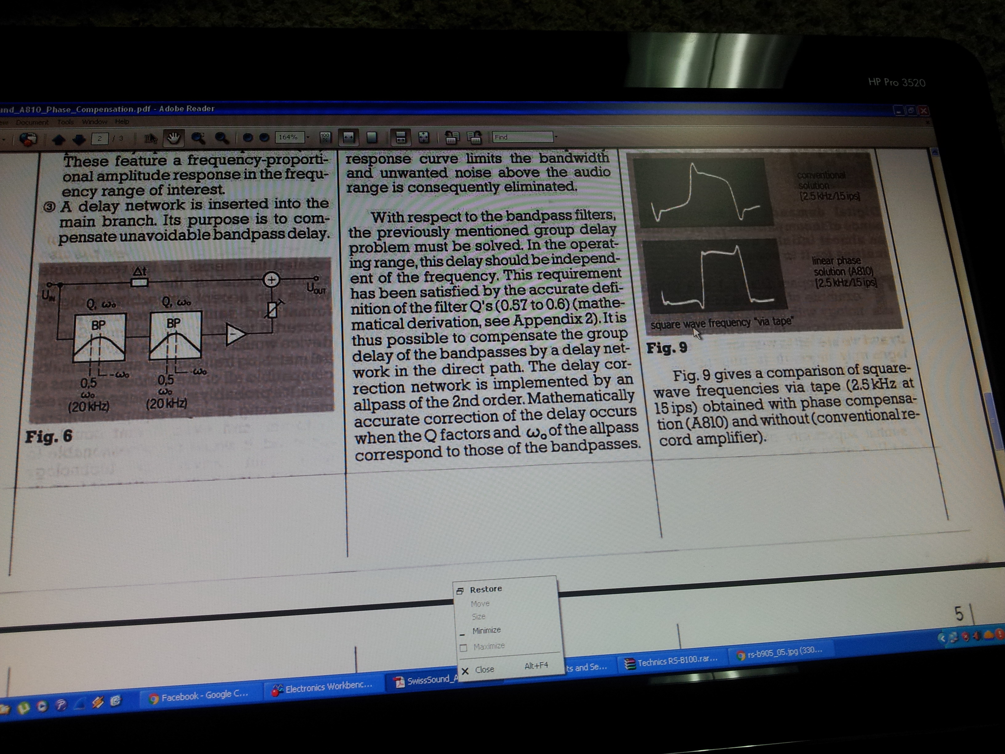 Every oscillation is caused by summing of the harmonics to the final product signal.
 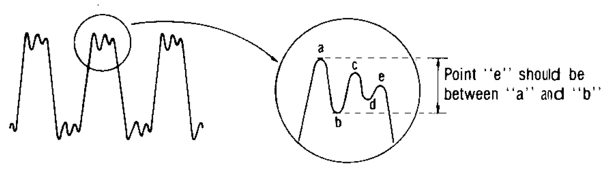 The result is accurate waveform fidelity, so you hear more from the high frequency linearity. An additional benefit is improved sound quality in second generation copies.
[1] J. Marco Egli, Phase compensation design consideration, Swiss Sound – A810 Audio
This review was created by Ph.D. Boris Ribov, who manage the LAB2104. The phase compensation was tested in the Laboratory of Embedded Systems (LAB2104) @Technical University – branch of Plovdiv. This custom made compensation circuit can be used not only in the recording chain. It can be used in the playback chain after the PB amplifier. That way it can be used to correct the problems of most standard pre-recorded tapes that are recorded without phase compensation.
Pingback: Reel-to-Reel Project @LAB2104 | LAB2104
Pingback: Nakamichi Dragon – Rebuild & Improvements | LAB2104