 Some experienced technician claims that the reference level specified in the service manual was wrong listed for all the Tandberg 3014A models. The service manual specify 580mV at the Dolby chip test points (TP4) when using standard Dolby test tape like Teac MTT-150 (400Hz-200nWb/m ANSI). The Tandberg level test tape is based on 1kHz/250nWb/m and is refer as 700mV on the same test points (TP4). Other cassette brands that use the same Dolby chip (LM1123) also specify 580mV for reference Dolby level using MTT150 test tape. Some of the cassette restoration technician claims that the reference Dolby level should be 680mV instead of 580mV. That will solve compatibility problems using Dolby C system. But the question is that Myth or Reality?
The 680mV reference level will be serious bug in the specification of the National Semiconductor Corp. Personally I do not believe that National Semi made this serious error when releasing the chip in the market. But it is a chance if they did not fully tested the reference design when they released the circuit in the datasheet. Personally I serviced several 3014A decks in the past 5 years and all were set for 580mV as described in the service manual. But we have to be sure is the 580mV is the right reference Dolby level. We decide to make more complex research into this issue. We create a test bench in the lab. We used the following signal chain – first a reference Dolby C encoder was used. The reference level of the external Dolby C encoder is known and is 387.5mV. The reference Dolby C circuit was taken from a well-aligned Nakamichi Dragon deck. The measurement will prove flat frequency response using mix tones with different frequencies (400Hz, 2kHz, 4kHz, 8kHz, 12.5kHz, 16kHz, 19kHz, 21kHz). The frequency response was measured with a software spectrum analyzer. All the tones have the same level in the input of the reference encoder.
 The signal from the output of the reference Dolby C encoder (pin 9 of the TEA0652) comes to a variable resistor divider to the input of the Tandberg 3014A Dolby decoder module (pin 11 of LM1123). We bypass the recording equalizer of the Dragon and also bypass the playback equalizer of the Tandberg 3014A. For that purpose the output of the encoder (pin 9 of the Dolby IC) goes directly to the input capacitor C752 of the Dolby decoder board (pin 11 of IC LM1123). That way we bypass the entire playback EQ and also the mute circuit.
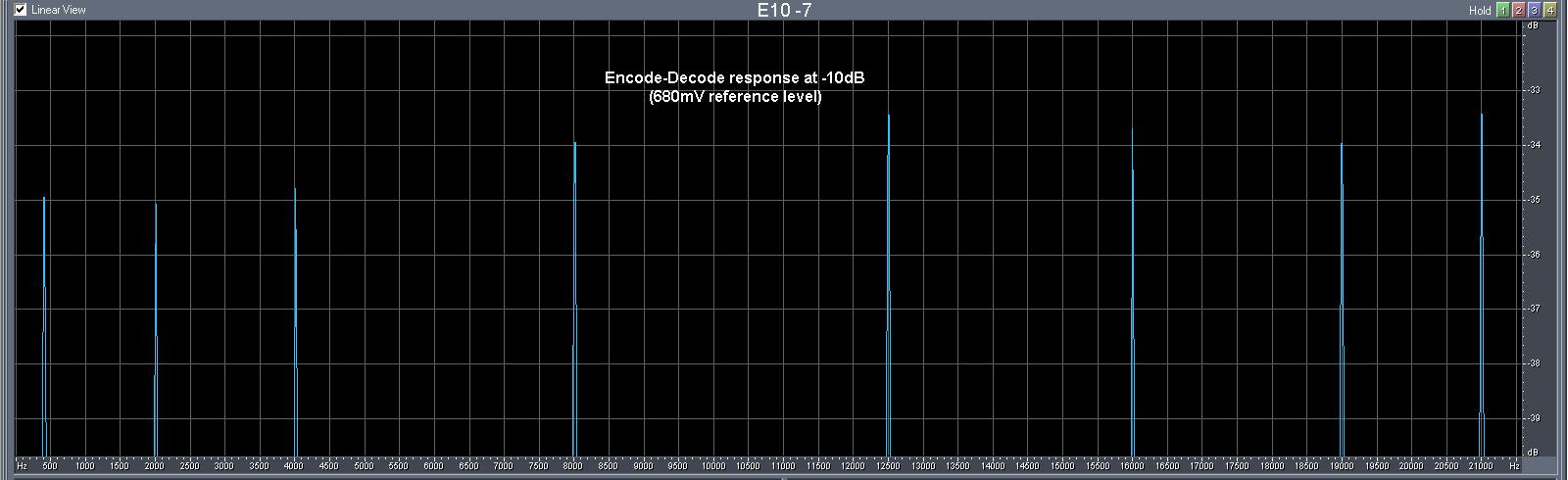
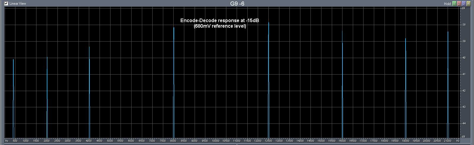
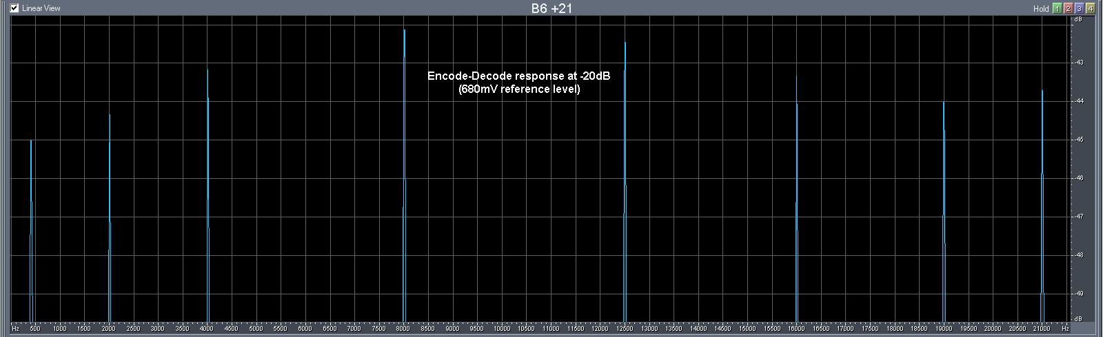
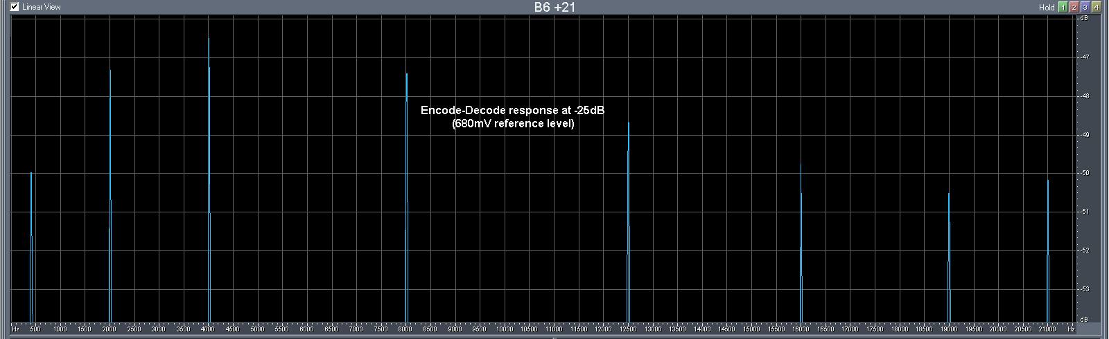
What was the scenario of the tests: first we will measure the spectrum chart of the frequency response after encoding-decoding process using Dolby C and reference level of 580mV. The second measurement will be made for the 680mV reference level. And now the question is how to set the reference level on TP4 of the Dolby decoder? The next steps will be used to set the reference level: First all the Dolby modules (encoder and decoder) have to be switched off by switches on the front panel of the Dragon (for the encoder) and on the Tandber (for the decoder module). An external 400Hz sine tone was set in the Line input of the Dragon deck. Then the reference level on the TP101/201 was measured to be 387.5mV and is set with the line-in level regulators of the deck. The variable divider connected to pin 9 of the encoder was set that way to get the expected Dolby reference level on the test point TP4 on the decoder module (580mV). Now we have well defined working parameters of the decoder and also of the known encoder. Now we have to switch on Dolby C system on both encoder and decoder modules. From external DDS generator we put the mixed signal (different sine frequencies with equal level) and at the same time we will measure the frequency chart at the output of the decoder module for different input level of the encoder. We made several measurements for +5dB, 0dB, -5dB, -10dB, -15dB, –20dB and -25dB of the mixed frequency tones. Now look at charts at the output of the decoder when Dolby C was activated at reference level of 580mV:
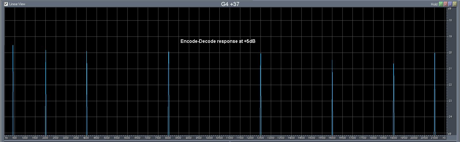
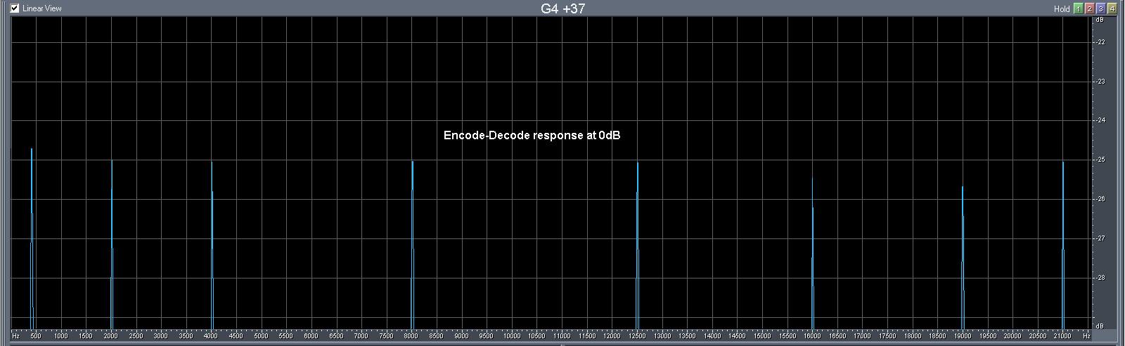
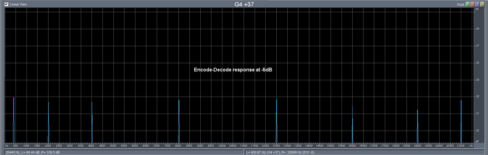
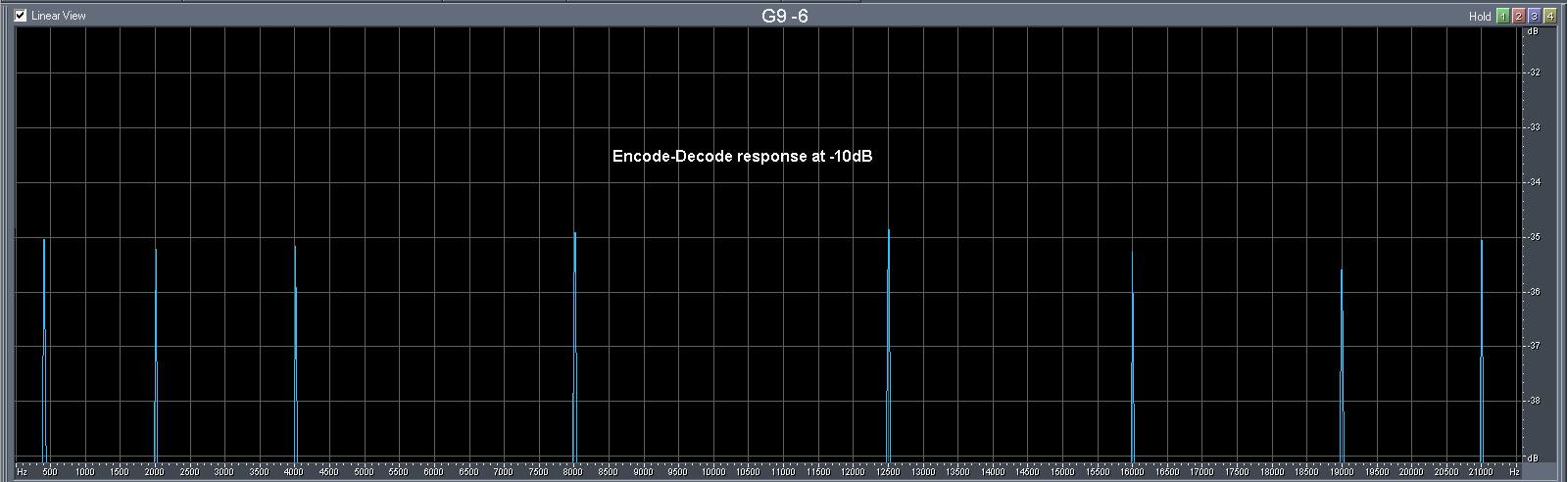
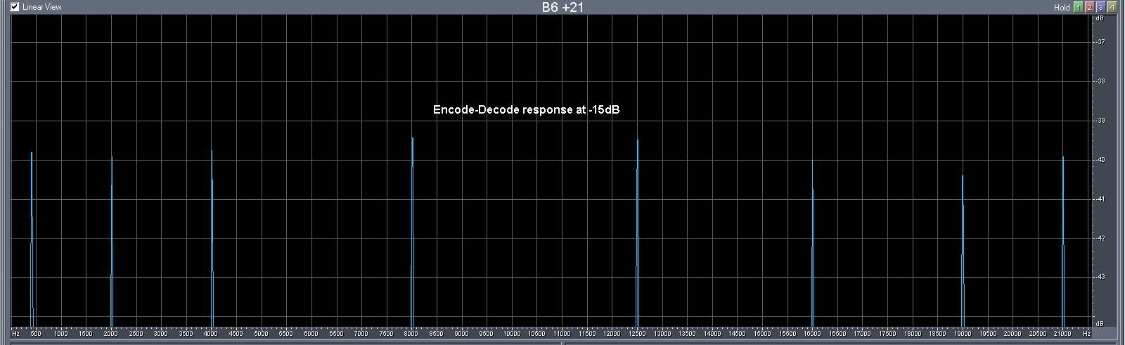
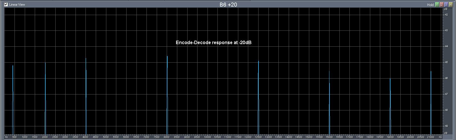
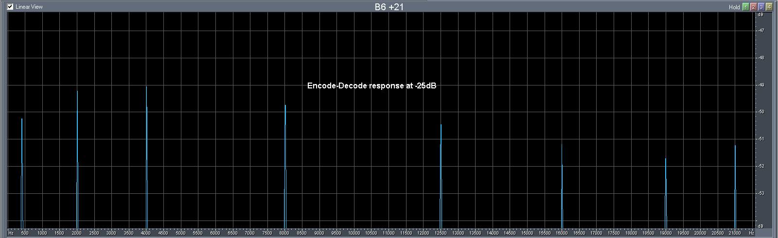
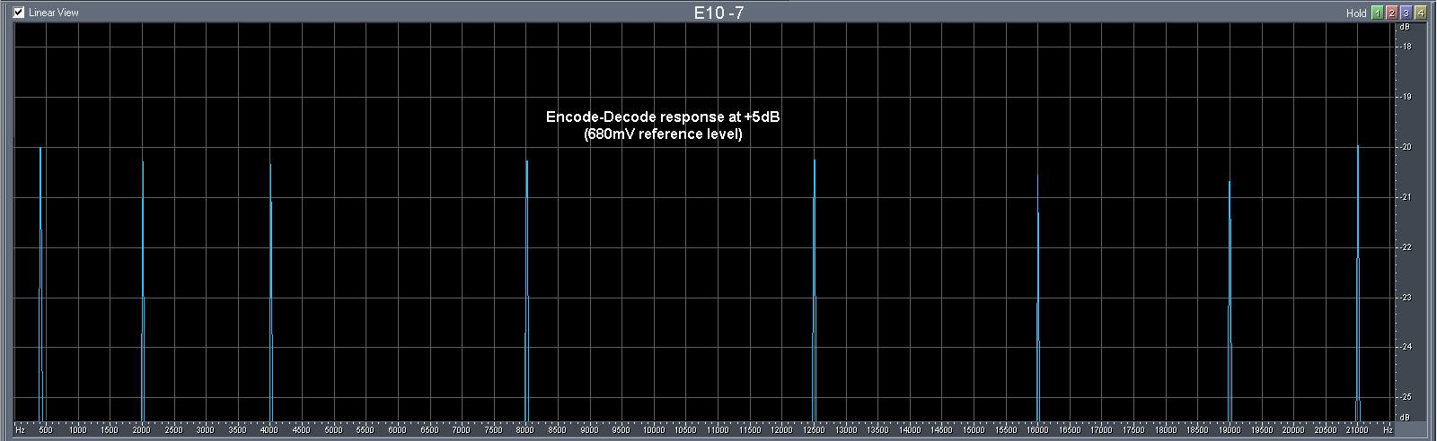
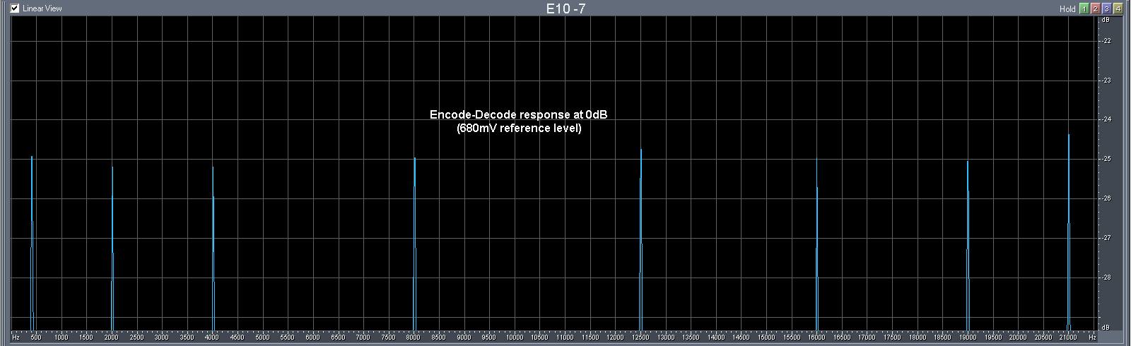
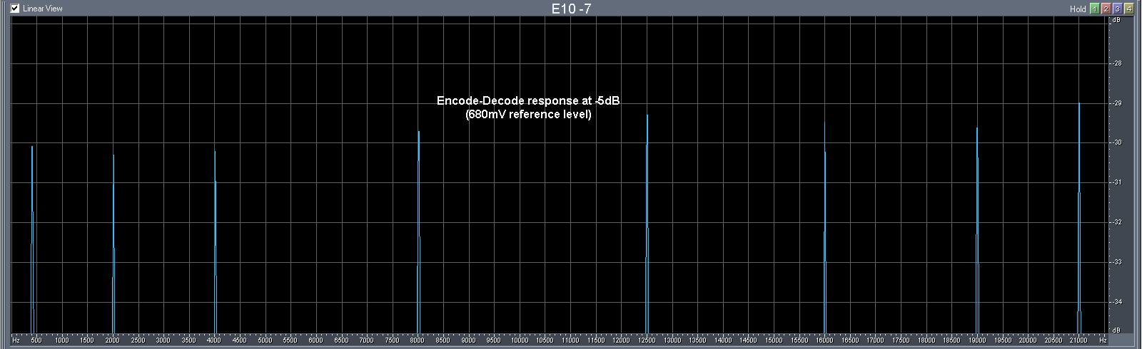
As can be seen the 580mV reference level confirms the near 1:1 decoding after encoding. You can see that the 680mV reference level made some HF boost in the decoding process especially on the lower input levels. Maybe if you have old recordings the increased reference level to 680mV is good for the compensation of the demagnetization of the content but it is not the right engineering solution for setting the machine to the standards. Let look at the charts at the output of Dolby C decoder when it was activated for 680mV:
On the other hand the 3014A has very close to the last Prague IEC frequency chart. A Teac MTT-256 test tape was used to measure the Playback frequency response. So it does not require modifications or compensation of the playback equalizer.
As a conclusion, the measurement confirms that the reference level of 580mV on the TP4 that was specify by the Tandberg is the right reference level. That is why we will continue to set the 3014A machines for 580mV and will discard any recommendation for 680mV even by the client personal requirements.
Pingback: Tandberg 3014A: rebuild & review | LAB2104